LabPET II TECHNOLOGY

from one success to another

After the international success of the LabPET I it was only natural for the team to consider the numerous ideas, recommendations and feedbacks collected from many of the best research centers across the globe to try to develop second generation of high quality preclinical PET scanners. The second generation of the LabPET II scanners aimed to reach nothing less than the best image quality on the market. This ambitious project to develop a new generation of small animal PET scanner was only possible by bringing together the research teams at Université de Sherbrooke with over seven other organizations and key suppliers across North America. This version of the LabPET is an improvement of the LabPET I as all the performances were increased, without affecting the much appreciated high stability and reliability of the scanners. Its modular approach enables the creation of PET scanners of different diameters and lengths to adapt perfectly to all the type of small animal studied while using the same detectors and the same key components. The LabPET II makes it possible to measure and detect details requiring true submillimetric spatial resolution, therefore enabling new possibilities and taking down barriers that were impossible to overcome before. 

overview of technology

The LabPET II is based on 128-channel detection module consisting of four monolithic arrays of 4 × 8 avalanche photodiodes (APD) individually coupled to an 4 × 8 scintillator array. This configuration enables up to ~37 000 channels to be implemented in LabPET II compared to ~ 4600 channels in LabPETTM I (previous generation) for the same scanner diameter and axial length (16 cm × 12 cm). To achieve such channel integration, the front-end electronics has been scaled down in a 64-channel, mixed-signal, Application Specific Integrated Circuit (ASIC) based on the TSMC CMOS 0.18 μm technology.

Detection module

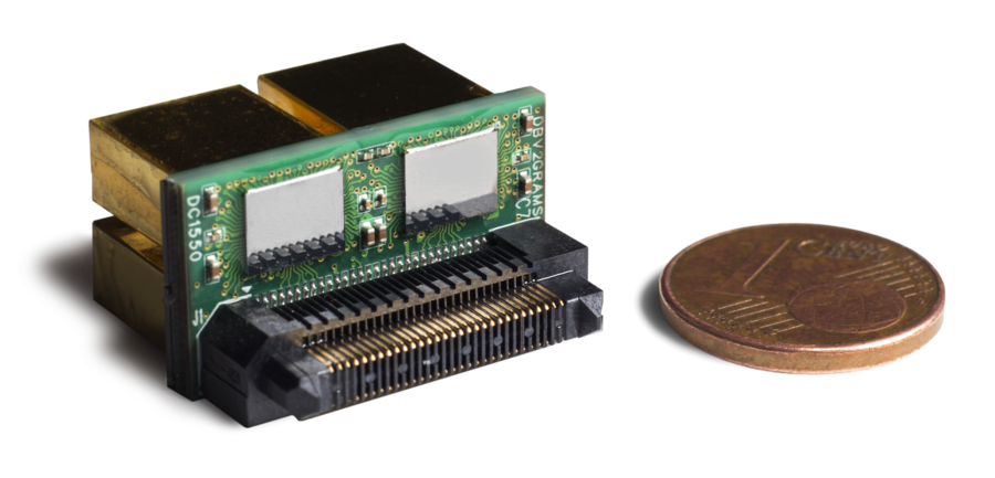
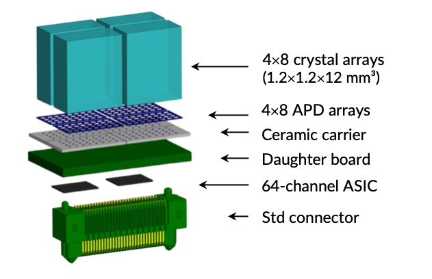
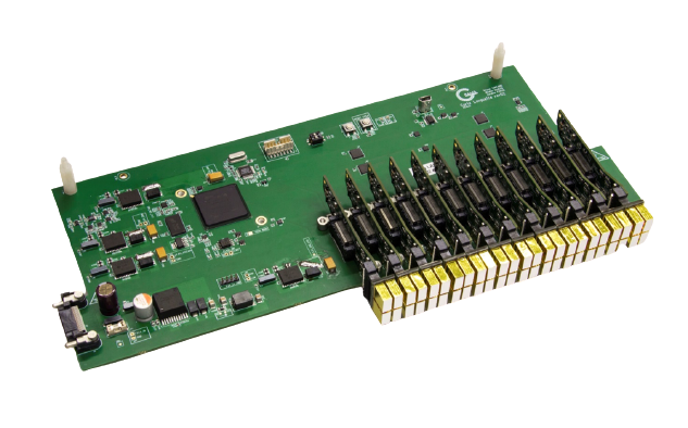
The LabPET II detection unit is a 128-channel detector module based on four arrays of elementary unit. Each unit consists of 4×8 array of 1.12×1.12×12 mm3 LYSO (Lu1.9 Y0.1 SiO5) scintillator pixels individually coupled with a monolithic array of 4×8 avalanche photodiodes (APD). A custom electronic board acts as an interposer between the four arrays of detectors and two 64-channel, mixed-signal, Application Specific Integrated Circuit (ASIC) to form a 128-channel readout unit.

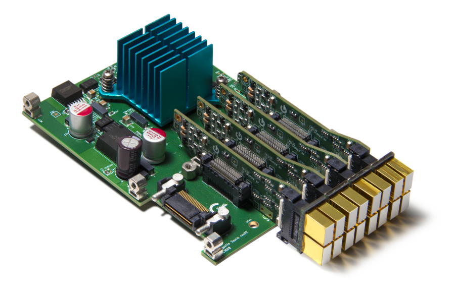
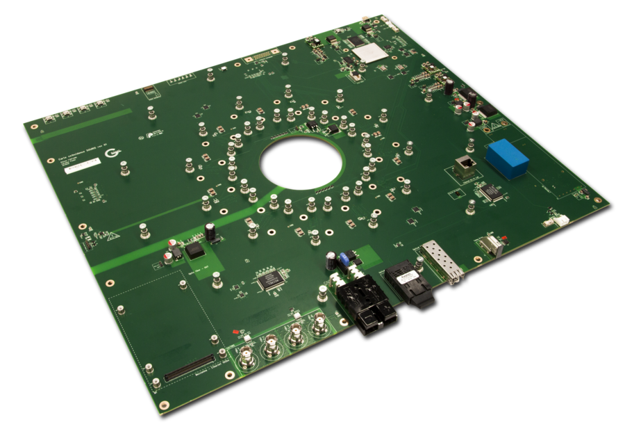
The ASIC characterizes detected events with both timestamp and energy along with their pixel address. These features are extracted using a time-over-threshold (TOT) scheme, a technique based on the time an analog signal spends over a fixed threshold. This technique allows assigning a timestamp to an impulse regardless of its amplitude. A DAQ system was designed to interface the ASICs and process PET data in real-time.

ONE TO ONE COUPLING PIXELATED DETECTORS

The philosophy behind the LabPET II detectors was to reach the best physically possible spatial resolution to obtain the best image quality. With such an objective for the new generation of PET scanners, the required technology complexity level sure had to be much higher than other mainstream technologies based on the use coding or shared electronic. Once developed the first results obtained, it quickly became clear that the choice of the high complexity approach paid off: researches and studies shown the increasingly important difference in the image quality obtained with the pixelated LabPET II detectors. Namely, our module eliminates the spatial distortion (see above) which can drastically harm the quality of images and make it impossible to reach conclusions. Also, by using direct one to one coupling, no coding effect is created, which may not be directly seen in mire image or when imaging identical predefined structure but can impact negatively real preclinical imaging studies in real operational condition as the coding algorithms only bring estimates of organs and structure since they are of unpredictable forms. Moreover, the true spatial resolution obtained allows high intrinsic collection of data, very low dead time and optimize high max count rate.

daq architecture

The newly designed LabPET II DAQ architecture consists of 2 types of custom electronic boards based on Field Programmable Gate Array (FPGA). The first board is an Embedded signal processing unit and the second is a Coincidence, data communication and gating unit. This architecture was redesigned from a previous version, to take advantage of increasing FPGA resources, hence, reducing the number of electronic boards required and the scanner cost. This prototype geometry can fit 48 128-channel detection modules offering a total of 6144 acquisition channels with an expected maximum throughput of 3000 single events/s per channel. Therefore, the minimum required throughput for its DAQ is ∼18 M events/s. The architecture was designed following a tree topology. The Coincidence, data communication and gating board houses 12 Embedded signal processing boards. Each of the latter is connected to up to 4 detector modules for a 5 cm maximum axial length.

To support the higher data rate of LabPET II, a real-time, high throughput firmware is required. It was implemented in FPGAs using VHDL, together with an OS developed in C language within the FPGA embedded microprocessor.

LabPET II mouse scanner hardware with its FPGA-based custom electronic boards.
FPGA-based Embedded signal processing board with its 4 detector modules.
Coincidence PCB.
FPGA with 12 detector modules configuration.
Previous slide
Next slide

NaF PET Imaging